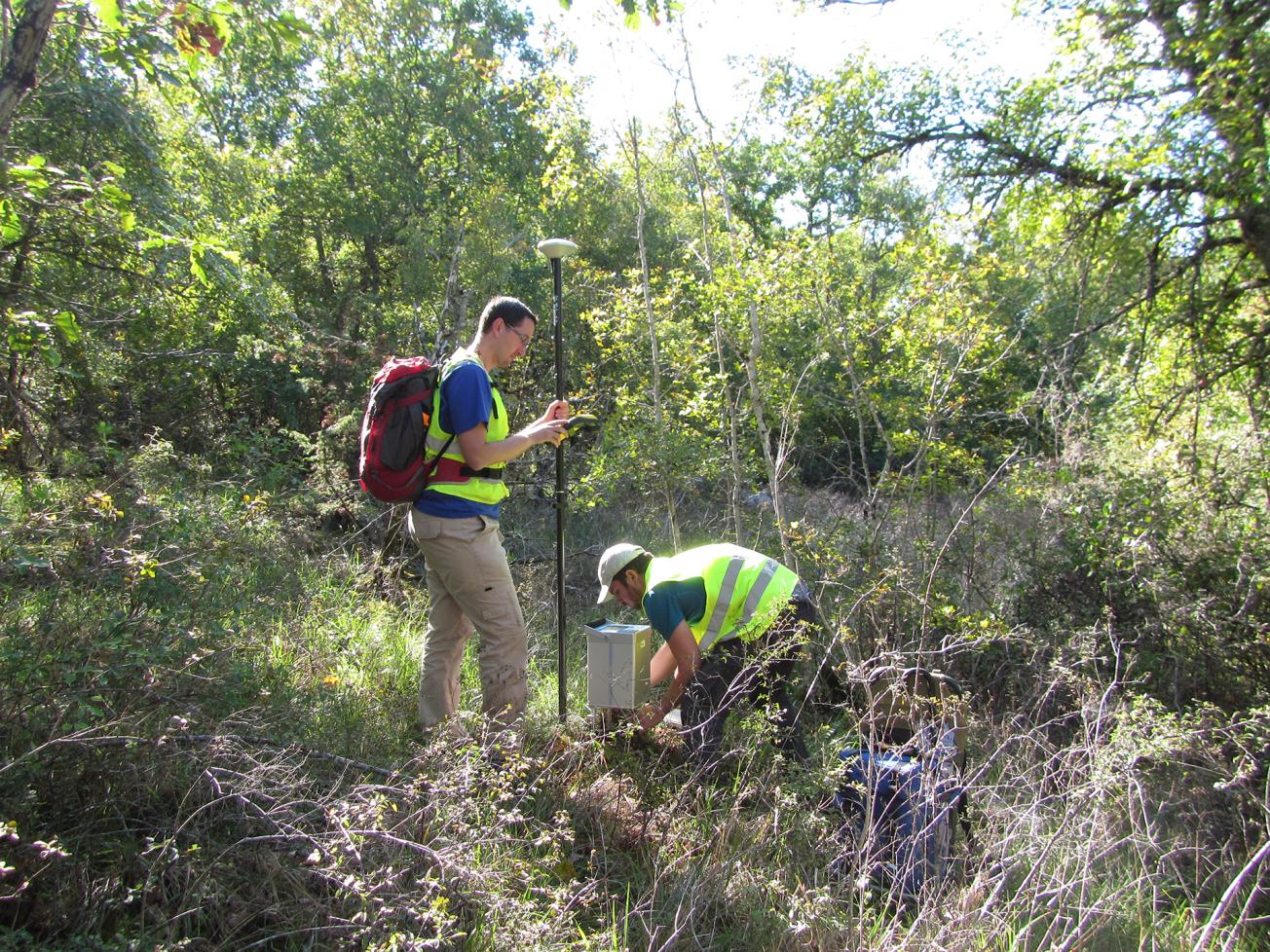
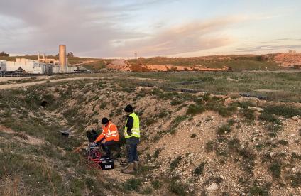
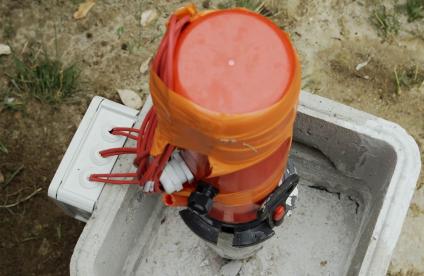
Gravimetric measurements and differential GPS location at the CEA site in Gramat.
© BRGM
To improve its management of the risks arising from the presence of an underground karst network, the CEA commissioned a study from the BRGM to improve geological knowledge of the site by detecting and characterising the underground karst system, with a particular focus on active conduits from upstream to downstream.
Speleological investigations had already been made, but only upstream from the facility, so that questions remained about the network taken as a whole. It was decided to combine several geophysical methods involving non-invasive techniques deployed from the surface. The survey began in 2014 with a combination of seismic reflection and refraction with electrical tomography of the conduits previously identified by the speleologists, to provide benchmarks for the investigation.
Tests having demonstrated the validity of the combined techniques, the BRGM turned in 2015 to the unexplored downstream parts of the system, covering an area of about 1 km2.
Combining seismics, electrical tomography and gravimetrics
Three methods were deployed that complement each other by focusing on different properties of the karst environment, adding gravimetrics to the two methods used for the first phase. Refraction and reflection seismics, which involve recording the propagation of shock waves produced by small explosions or physical shocks using a network of geophones, enabled us to produce a vertical section of the subsoil down to about 400m; the different rates of propagation tell us what kind of rock - weathered, karstified, etc. - the shock waves are travelling through. This gives us an initial approach to the structure and variations of mechanical properties in the subsoil.
Electrical tomography measures the propagation of an electrical current in the subsoil via electrodes placed along the segment under investigation. This produces an image of resistivity in the ground, which reflects variations caused by moisture content, weathering, lithological features, etc.
Finally, gravimetrics measure variations in the gravitational field - in this case every 50 metres using a GPS - arising from the way masses are distributed in the subsoil.
Key figures
-
6500.00linear meters of seismic and electrical profiles
-
556.00gravimetric points
-
1.00km2surface area
Conclusive results
Once collated into a GIS, the different results revealed significant anomalies along the axis of the main cavities in the site, reflecting the continuity of part of the karst system downstream from the industrial facility. The most significant geophysical anomaly detected by our methods along this axis was confirmed by drilling a borehole down into one large cavity and several smaller cavities and clay passages further down.
The complementary contributions of the three methods confirmed the relevance of combining seismics, electrical tomography and gravimetrics to investigate complex systems such as karsts. The results are conclusive for the upper karst system (down to 20 m) but further investigations are needed to characterise the anomalies detected at greater depths (150 m) in the flooded lower karst.
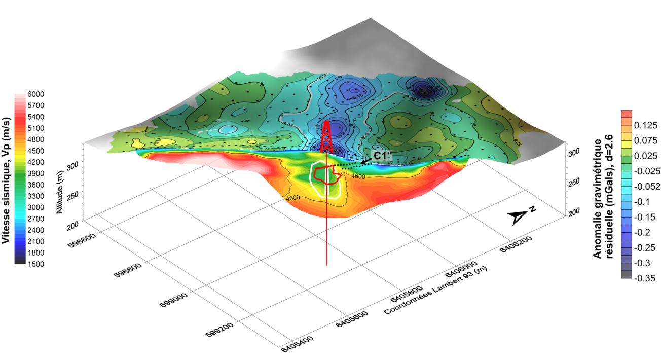
Methods used to locate and characterise the upper karst system.
© BRGM


1) gravimetric anomaly map (draped over the topography): the NW-SE axis, in blue, shows how the karst system continues downstream. 2) the vertical section showing seismic refraction speed outlines a rock mass with low mechanical characteristics (slow refraction anomaly in green). 3) the C1 conductive anomaly shown by electrical tomography (not shown) outlines an oblique weathered infiltration zone running up to the roof of the karstic cavity. Results confirmed by a control borehole: the contours of the cavity determined by sonar are outlined in red.